Calibrating Short Wave Infrared Sensors for Blowroom Contamination Removal
Calibrating short-wave infrared sensors using dynamic dual-band ratioing isolates white polypropylene from cotton lint while preventing false ejection cycles.

Optics
Standard visible-spectrum cameras miss much of the foreign material moving through pneumatic ducts with clean raw cotton. White polypropylene baling twine, clear polyethylene bale wrap, and translucent polyamide strapping share near-identical color coordinates with natural cotton fibers under quartz halogen lamps or visible light emitting diode bars. Sorting systems distinguish these synthetic polymers by turning to short-wave infrared absorption between 1000 and 2200 nanometers.
Cellulosic cotton fibers show strong hydroxyl peaks near 1450 nanometers and 1940 nanometers from bound moisture and cellulose monomers. Polyolefins lack hydroxyl groups altogether, displaying instead carbon-hydrogen stretching and bending overtones between 1710 and 1760 nanometers, with secondary combination bands from 2150 to 2320 nanometers.
Indium gallium arsenide line scan arrays pick up these spectral differences against reference illumination. Standard cameras operate from 400 to 700 nanometers, which works for optical brighteners or pigmented items via UV excitation and direct color contrast, but fails on colorless trash. SWIR detection evaluates chemistry instead.
As white polypropylene packaging film passes the scanner, reflected radiation is captured in two separate bands. The reference band at 1200 to 1300 nanometers reflects strongly off both polyolefins and raw cotton. At the 1730-nanometer measurement band, however, carbon-hydrogen bonds in the synthetic plastic absorb incoming photons heavily while the cotton continues to reflect, giving a dual-wavelength ratio that isolates clear plastics from raw lint.
Sensor hardware drifts quickly without active temperature stabilization. Indium gallium arsenide photodiodes produce substantial dark current as temperatures shift across a spinning mill’s opening line. On an uncooled array, baseline thermal voltage drifts by roughly six millivolts for every degree Celsius of ambient warming.
Blowroom temperatures frequently swing from 22 degrees Celsius at the start of the morning shift to 38 degrees Celsius under afternoon running loads. Without thermo-electric cooling, that thermal noise easily swamps the faint drop in reflectance caused by a polypropylene film fragment weighing under 0.5 milligrams.
A five-degree drift in sensor bench temperature alters the short-wave infrared ratio baseline by eight percent across uncooled photodiode arrays.
Signal quality depends heavily on viewing geometry as tufts accelerate across the quartz window. Mounting illumination bars at 45-degree angles relative to the optical receiver axis suppresses specular glare from slick plastic films, which otherwise mirrors light into the photodiodes and saturates every channel. Diffuse reflectance is what carries the absorption signal.
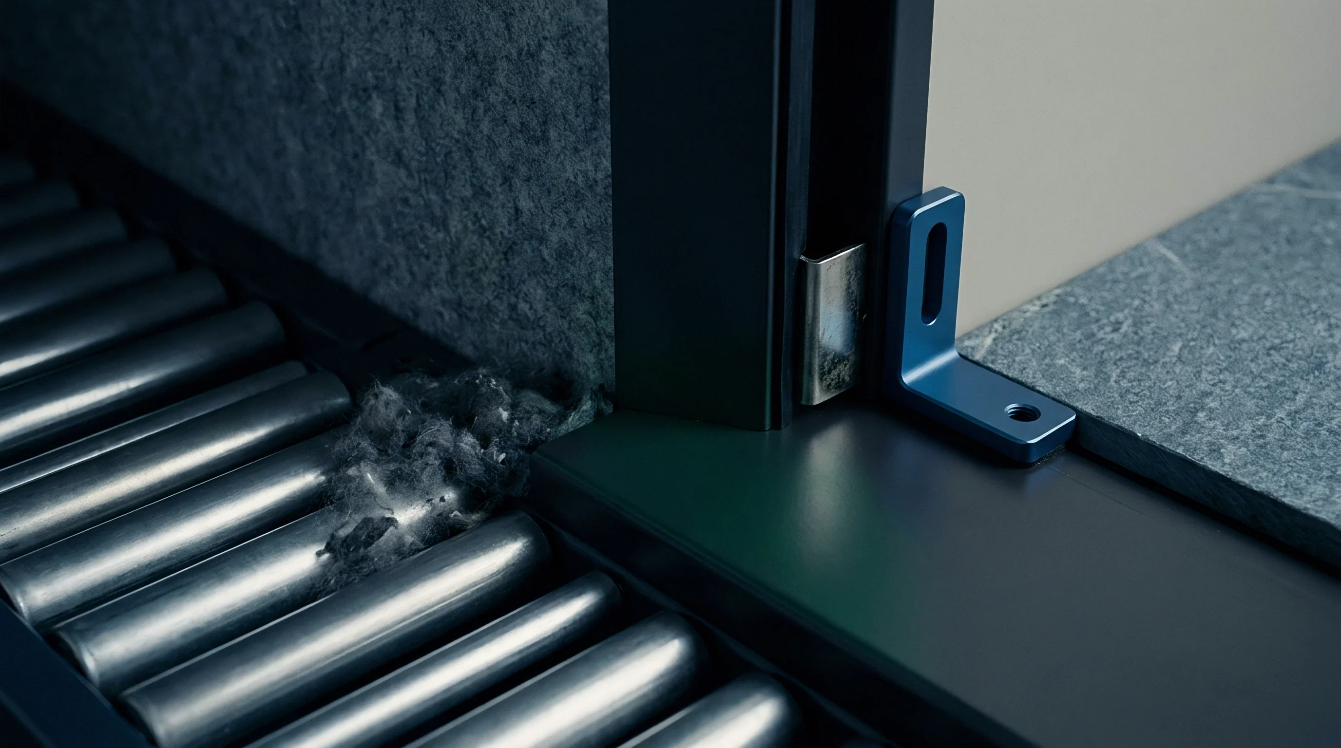
At the same time, quartz panes must be kept clear of static-clinging lint and cotton wax. Accumulated wax builds a hydrocarbon layer across the glass that reads as false polyolefin contamination across the full array. Cleaning the quartz with isopropyl alcohol every eight operating hours prevents this build-up; skipping cleanings pushes false rejections up until pneumatic valves blow three percent of good lint straight to the waste house.

Duct
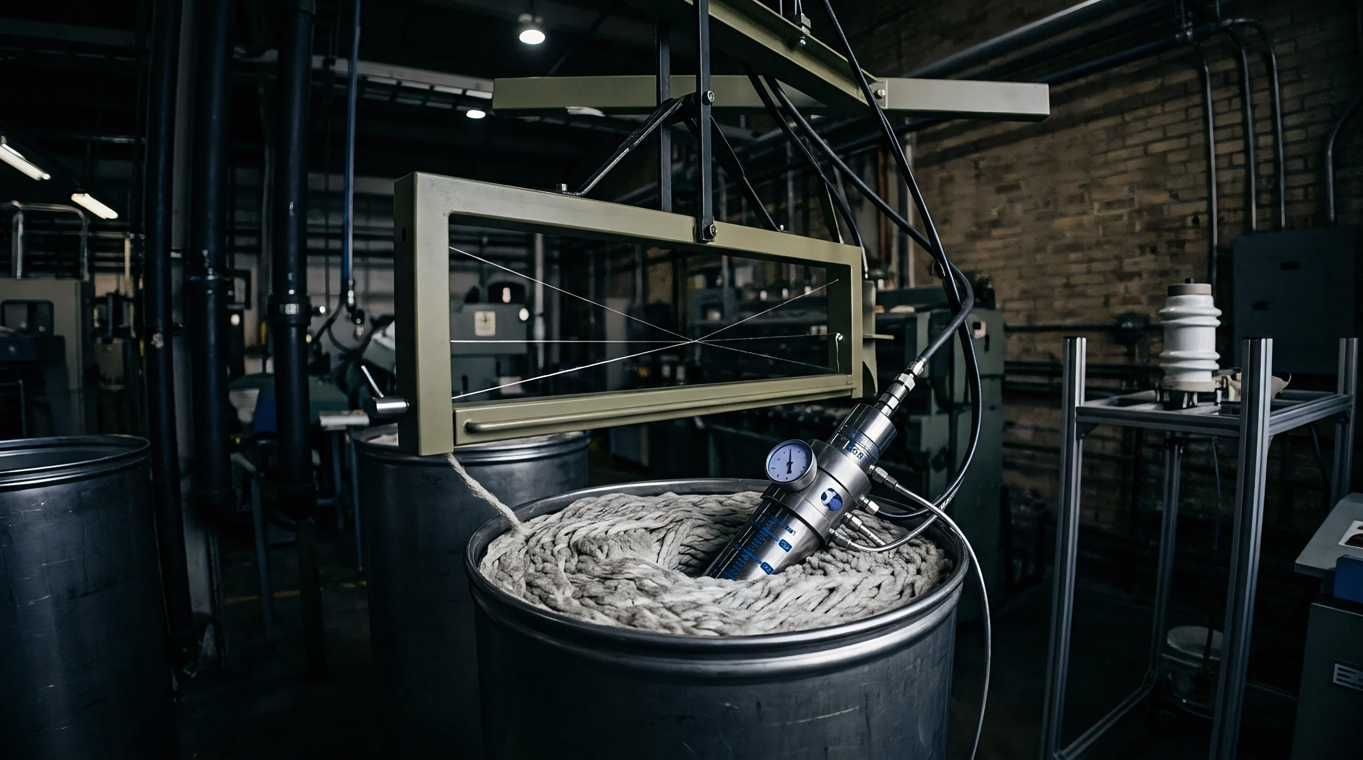
Tuft velocity through the conveying duct dictates the integration time left for the SWIR array. Fans push opened cotton through the rectangular inspection chute at 10 to 16 meters per second, meaning a two-millimeter contaminant clears the scan line in under 200 microseconds. Line scan rates have to run at 10 to 15 kilohertz simply to resolve two successive pixel lines on that moving piece.
Dropping scan frequencies below eight kilohertz opens physical blind gaps down the chute, letting narrow polypropylene strands slip past between exposures.

Where Air Turbulence Deflects Passing Contaminants?
Static pressure variations across the duct profile alter where particles fly through the viewing window. Cotton tufts hold to central streamlines, but denser polypropylene fragments swing outward toward duct walls under centrifugal force from upstream elbows. To keep presentation uniform, circular ducting transitions into a flattened rectangular chute.
The inspection zone depth must stay under 80 millimeters; any deeper, and bulky tufts hide light films underneath them, masking the plastic from both infrared lighting and sensor line scans.
| Transport Air Velocity | Line Scan Frequency | Pixel Exposure Time | Spatial Resolution Downstream | Ejection Latency Window |
|---|---|---|---|---|
| 8.0 meters per second | 8.0 kilohertz | 125 microseconds | 1.00 millimeter | 32 milliseconds |
| 10.0 meters per second | 10.0 kilohertz | 100 microseconds | 1.00 millimeter | 25 milliseconds |
| 12.0 meters per second | 12.0 kilohertz | 83 microseconds | 1.00 millimeter | 21 milliseconds |
| 14.0 meters per second | 15.0 kilohertz | 66 microseconds | 0.93 millimeter | 18 milliseconds |
| 16.0 meters per second | 20.0 kilohertz | 50 microseconds | 0.80 millimeter | 15 milliseconds |
Detection depends directly on how thoroughly the raw cotton has been opened. Dense clumps scatter infrared light erratically and attenuate the signal before it reaches embedded synthetics. Placing optical sorters right after fine opening rather than directly behind bale plucking equipment yields far better presentation.
Fine openers break cotton into individual tufts averaging under 15 millimeters in diameter, letting the sensor collect reflected light through the tuft’s full volume instead of skimming the surface.
Mechanical vibration transmitted from high-speed fans degrades camera focus over operating cycles. Rigid duct mounts couple blower motor vibrations directly into optical camera gantries. Heavy dampening isolators isolate the optical rail from sheet metal ductwork.


Threshold
Establishing detection thresholds means separating fiber variation from actual foreign contaminants. Raw bales brought to the laydown show moisture regain between 5.5 and 8.5 percent under standard commercial conditions. Because water absorbs heavily at 1450 and 1940 nanometers, wet cotton lowers broad-spectrum signal return.
If the system relies on a static threshold calibrated on dry stock, damper tufts trip the sensor as synthetics and waste compressed air.

Why Moisture Swings Alter Absorption Thresholds?
Dynamic ratio calculation prevents false triggers from moisture swings by tracking relative absorption rather than raw intensity. Two photodiode channels sample reflected SWIR light concurrently: a measurement channel at 1730 nanometers for hydrocarbon absorption, and a reference channel at 1280 nanometers where cellulose and moisture curves remain relatively flat. The processing unit calculates a continuous ratio between the two signals.
For clean cotton, this ratio stays steady even as moisture drifts between 6.0 and 9.0 percent. Polypropylene or polyethylene passing the sensor causes an immediate downward spike. Calibrating the trigger involves gathering statistical baseline data on the active lot and placing the threshold three standard deviations below the clean-fiber mean.
That margin suppresses nuisance firings while still catching polyolefin pieces as small as one square millimeter.
- Dark Current Capture closes optical shutters to record ambient thermal voltages across all photodiode pixels.
- White Reference Target positions a standardized polytetrafluoroethylene calibration bar into the optical path to set baseline unity gain across the active spectral band.
- Cotton Stock Normalization samples clean running stock for two minutes to balance the dynamic ratio quotient to exactly 1.00 across all channels.
- Sensitivity Boundary Assignment programs the lower rejection threshold between 0.82 and 0.88 based on target yarn cleanliness criteria.
- Pneumatic Test Verification fires each individual air nozzle in sequence to confirm air delivery pressure exceeds 0.6 megapascals.
Solvent extraction tests show raw cotton typically carries between 0.4 and 0.8 percent natural wax by weight. Because these ester waxes absorb faintly around 1725 nanometers, right next to the polypropylene signature, high-wax cotton varieties shift the baseline ratio downward. Adjusting sensitivity thresholds without checking fiber wax content leads to persistent misfires.
Raw cotton with wax content above 0.75 percent suppresses the baseline optical ratio by 0.04 points.
Before starting production, technicians check sensor calibration curves using standard test tabs. Two-millimeter-wide strips of white polypropylene are pulled through an offline suction tube to verify valve response, which the system logs to the nearest microsecond. Any loss in optical sensitivity shows up immediately as missed film strips.
Commercial yarn contracts routinely mandate zero foreign matter faults per 100 kilometers during automated winder audits.

Ejection
Optical detection is useless without precise physical ejection. Pneumatic nozzle manifolds sit 200 to 500 millimeters downstream from the scan line, giving the programmable logic controller time to map particle coordinates, estimate transit velocity, and fire the targeted solenoids. If duct air velocity wavers, however, the contaminant reaches the nozzle bar out of sync with the air pulse.
High-speed solenoid nozzles line the manifold at 10 to 15 millimeter intervals across the chute width. When the SWIR sensor spots polypropylene, the controller reads the horizontal pixel coordinates and fires two or three neighboring nozzles over that position. Actuating a single nozzle is risky, as tumbling particles can shift laterally in turbulent air.
Valve open times run between 15 and 30 milliseconds.
| Operating Air Pressure | Solenoid Actuation Time | Valve Open Duration | Lint Waste Per Blast | Removal Efficiency |
|---|---|---|---|---|
| 0.45 megapascals | 4.5 milliseconds | 35 milliseconds | 3.8 grams | 81.2 percent |
| 0.50 megapascals | 3.8 milliseconds | 30 milliseconds | 3.2 grams | 88.6 percent |
| 0.60 megapascals | 2.5 milliseconds | 20 milliseconds | 1.8 grams | 96.4 percent |
| 0.65 megapascals | 2.2 milliseconds | 18 milliseconds | 1.5 grams | 98.1 percent |
| 0.70 megapascals | 2.0 milliseconds | 15 milliseconds | 1.2 grams | 98.5 percent |
Overly long blast durations dump valuable fiber. Holding a valve open for 40 milliseconds throws out as much as five grams of good cotton along with a speck of plastic. On a line running 800 kilograms per hour, 200 ejections an hour rapidly turns into significant waste.
Trimming blast duration to 15 milliseconds drops fiber loss to roughly one gram per firing without failing to reject the particle.
Air pressure set above target values preserves lint while blowing contaminants clean into the extraction duct.
Manifold pressure demands steady regulation. Compressed air feed must remain above 0.60 megapascals; dropping below 0.50 megapascals delays valve opening by two milliseconds. That delay is enough for the contaminant to blow past the nozzle opening before the air blast reaches full force, letting plastic travel straight through to the carding room.
- Pressure Drop Failure occurs when line pressure drops beneath 0.55 megapascals during concurrent multiple-valve firing cycles.
- Moisture Contamination Risk introduces oil droplets and condensed water into pneumatic manifolds, destroying solenoid responsiveness.
- Nozzle Orifice Clogging develops when lint dust settles inside inactive jet openings, reducing blast air velocity by 30 percent.
- Timing Misalignment Defect arises when upstream transport fan speed drifts without automatic recalculation of sensor-to-nozzle delays.
Timing faults show up clearly in card room waste data as sudden jumps in flat-waste contamination. When ejection pulses miss, synthetic tape passes into the carding machine’s licker-in roll, where high-speed wire teeth shred film into thousands of microscopic fibrils. Once these disperse evenly through the sliver, downstream optical sorters can no longer remove them.

Audit
Winding floor audits provide the final check on blowroom SWIR sorting performance. Electronic yarn clearers fitted with optical and capacitive sensors inspect yarn continuously at speeds topping 1200 meters per minute. These clearers classify foreign matter faults across defined length and optical density channels, while Classimat testing quantifies residual defects per 100,000 meters of spun yarn.
| Blowroom Optical Configuration | Short Polyolefin Faults | Long Plastic Filaments | Winder Cut Frequency | Total Defect Mass |
|---|---|---|---|---|
| Standard Visible Light Only | 42.5 cuts | 18.2 cuts | 60.7 per 100 km | 14.8 milligrams |
| Visible Light Plus Ultraviolet | 36.1 cuts | 15.4 cuts | 51.5 per 100 km | 11.2 milligrams |
| SWIR Without Dynamic Calibration | 14.2 cuts | 4.8 cuts | 19.0 per 100 km | 3.6 milligrams |
| SWIR With Dual Ratio Calibration | 1.8 cuts | 0.4 cuts | 2.2 per 100 km | 0.5 milligrams |
Spinning operations guarantee carded and combed yarns against stringent foreign matter limits. Knitting and weaving plants routinely reject shipments that log more than two foreign fiber cuts per 100 kilometers. Clear or white polypropylene passes greige fabric inspection unseen, but resists reactive dyestuffs meant for cellulosic fibers during dyeing.
The resulting undyed plastic flecks show up as bright white specks across finished knit goods, forcing entire lots into lower commercial grades.
Financial losses from contamination easily outstrip the cost of blowroom fiber waste. Finished knit fabric downgraded from first to second quality suffers price cuts of 30 to 50 percent per kilogram. On a single 20-tonne delivery of dyed single jersey cloth, scattered polyolefin fragments create massive financial exposure.
Supply contracts typically assign full product liability to the spinning mill once winder fault logs confirm the contamination originated in the yarn.
Mill staff track daily logs covering baseline sensor ratios, blast counts, and rejected waste weights. When properly tuned, blowroom sorters maintain contamination removal rates above 95 percent without discarding excessive spinnable fiber. Comparing daily blowroom rejection counts against winder cut data keeps opening-line performance verified and prevents expensive surprises downstream.