Finite Element Analysis of Hydrothermal Yarn Strain in Jet Dyeing
Finite element modeling reveals hydrothermal yarn strain in jet dyeing stems from drag forces exceeding wet elastic limits near polymer glass transition.
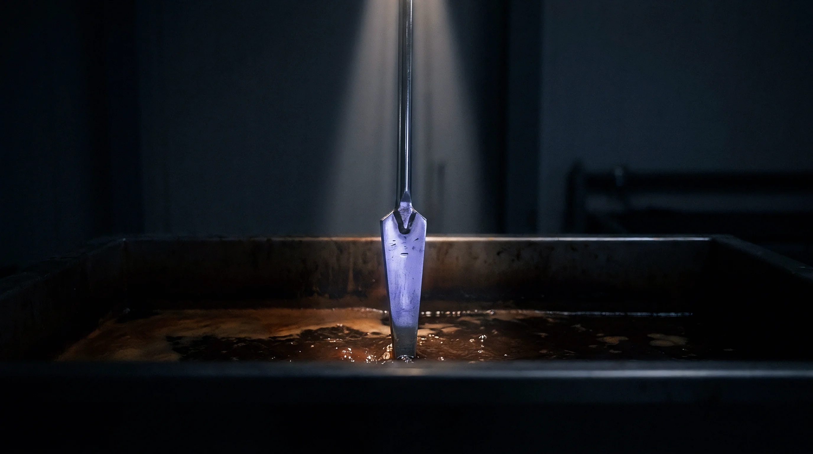
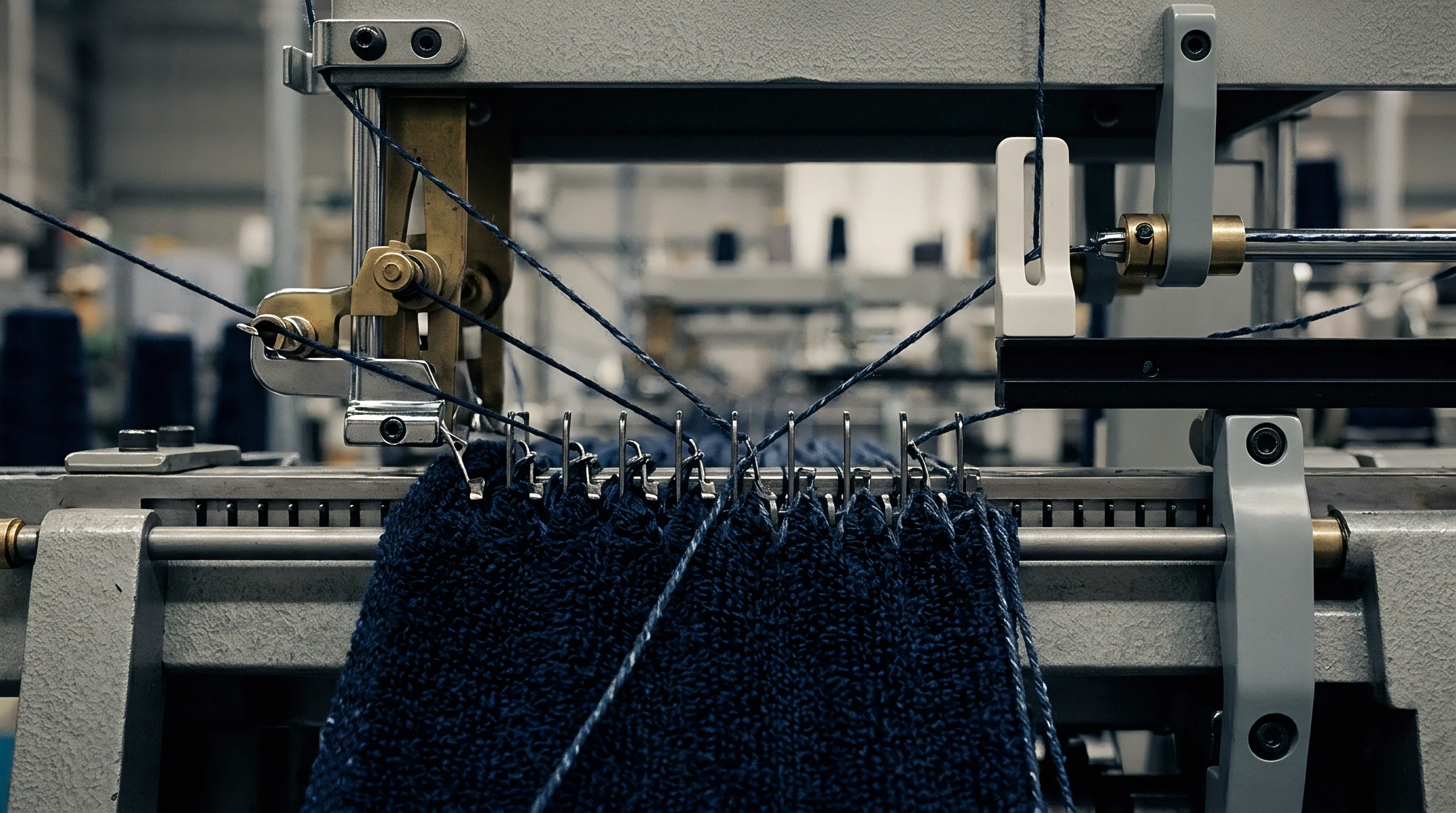
Nozzle
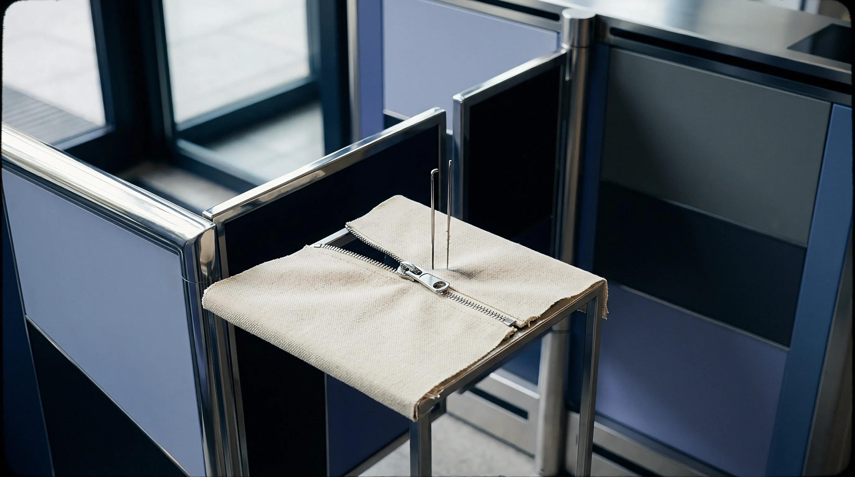
Venturi Transport and Hydraulic Drag Mechanisms
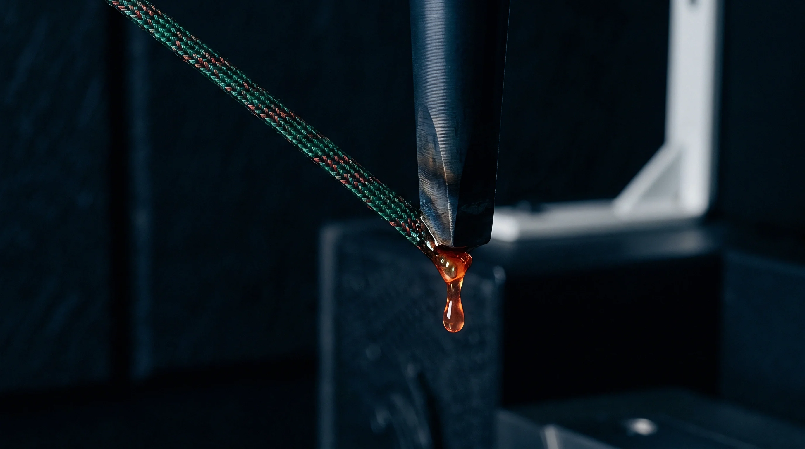
In high-temperature pressure vessel processing, fluid momentum propels the fabric rope through an restricted circular orifice to generate continuous circulation. The primary force driving the textile rope originates from static pressure differential converting into dynamic fluid kinetic energy inside the constriction. Dye liquor entering the chamber under pump pressures between 0.2 MPa and 0.4 MPa accelerates as the internal cross-sectional area contracts, generating high velocity shear layers along the fluid-yarn interface.
Polymer chains slip under hydraulic drag. Water acts as a plasticizer. Fluid friction transfers kinetic energy to the spun or filament bundle, pulling the bulk rope forward while imposing continuous longitudinal tensile loads.
The total tensile pull experienced by individual yarns during passage depends on liquor velocity, nozzle diameter, fluid density, and bath temperature. As temperature climbs toward 130°C in polyester dye cycles, fluid viscosity decreases from approximately 1.00 mPa·s at ambient room temp down to 0.21 mPa·s. Lower viscosity alters the boundary layer thickness surrounding the yarn surface, reducing specific drag per unit surface area while requiring higher volumetric flow rates to maintain rope transport speed.
Fabric speed matches liquor velocity.
Matching liquor circulation speed to mechanical reel perimeter speed prevents drag-induced tension spikes at the convergence zone.

Tensile Gradient Distribution across the Rope Geometry
Tensile stress inside the jet vessel is far from uniform across the circulating fabric loop. Peak tension occurs at the entry cone of the constriction zone where the stationary or slower-moving rope abruptly accelerates to match fluid velocity. Axial strain accumulates with cycle count.
At this localized impact area, individual yarns experience instantaneous tensile forces reaching 0.15 cN/dtex to 0.35 cN/dtex, depending on total liquor flow rate and rope linear mass density. Secondary stress concentrations emerge when the wet rope exits the transport tube and impacts the baffle plate inside the main storage chamber.
The cross-sectional strain distribution within the rope varies radially. Boundary yarns situated on the outer periphery of the twisted fabric rope absorb the direct momentum of incoming fluid streams, suffering local micro-stretching and shear deformation. Core yarns inside the inner bundle experience compressive stresses from outer filament consolidation, yielding non-uniform structural extension across the strand assembly.
Rope rotation prevents permanent creasing. If rope rotation halts, localized axial tension degrades specific segments of the yarn continuous length, causing structural width loss and uneven linear density.
The following failure modes illustrate mechanical and structural defects generated by uncalibrated fluid velocity inside jet transport channels:
- Micro-filament rupture occurs when instantaneous hydrodynamic drag forces exceed individual filament tenacity during rapid acceleration through the throat.
- Longitudinal yarn elongation develops under continuous tensile loading above the elastic yield limit, inducing permanent structural thin spots.
- Cross-sectional yarn flattening stems from localized fluid compression forces squeezing the flexible strand against internal tube walls.
- Surface filament abrading arises from relative velocity differentials between boundary fibers and fast-moving liquor boundary layers.
Dyehouse machinery builders often claim that modern air-assisted or low-liquor jet vessels eliminate longitudinal tension entirely, yet physical fluid mechanics dictates that kinetic energy transfer to a wet textile structure inevitably generates measurable tensile shear stress along every continuous filament bundle.

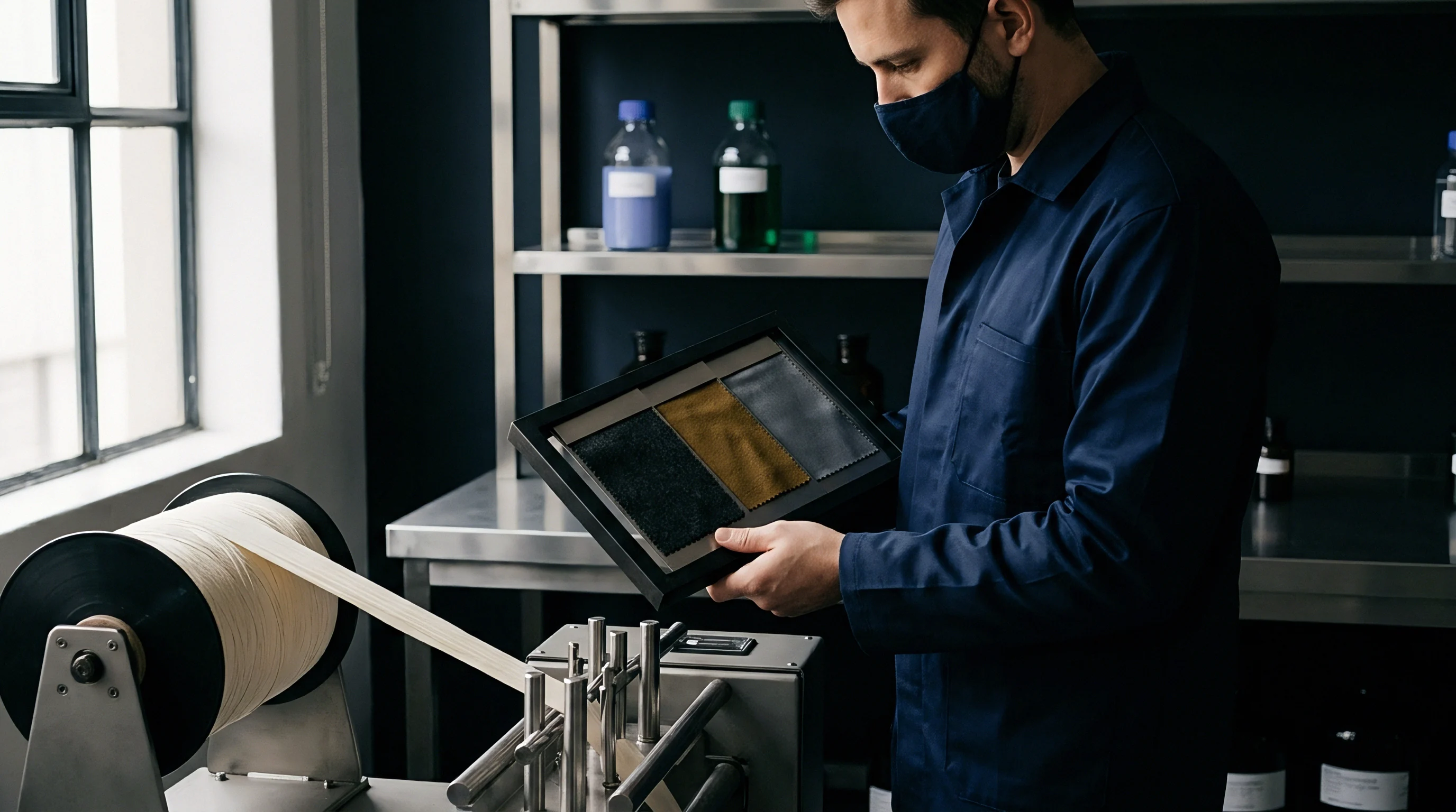
Relaxation
Thermodynamic Softening and Polymeric Creep Dynamics
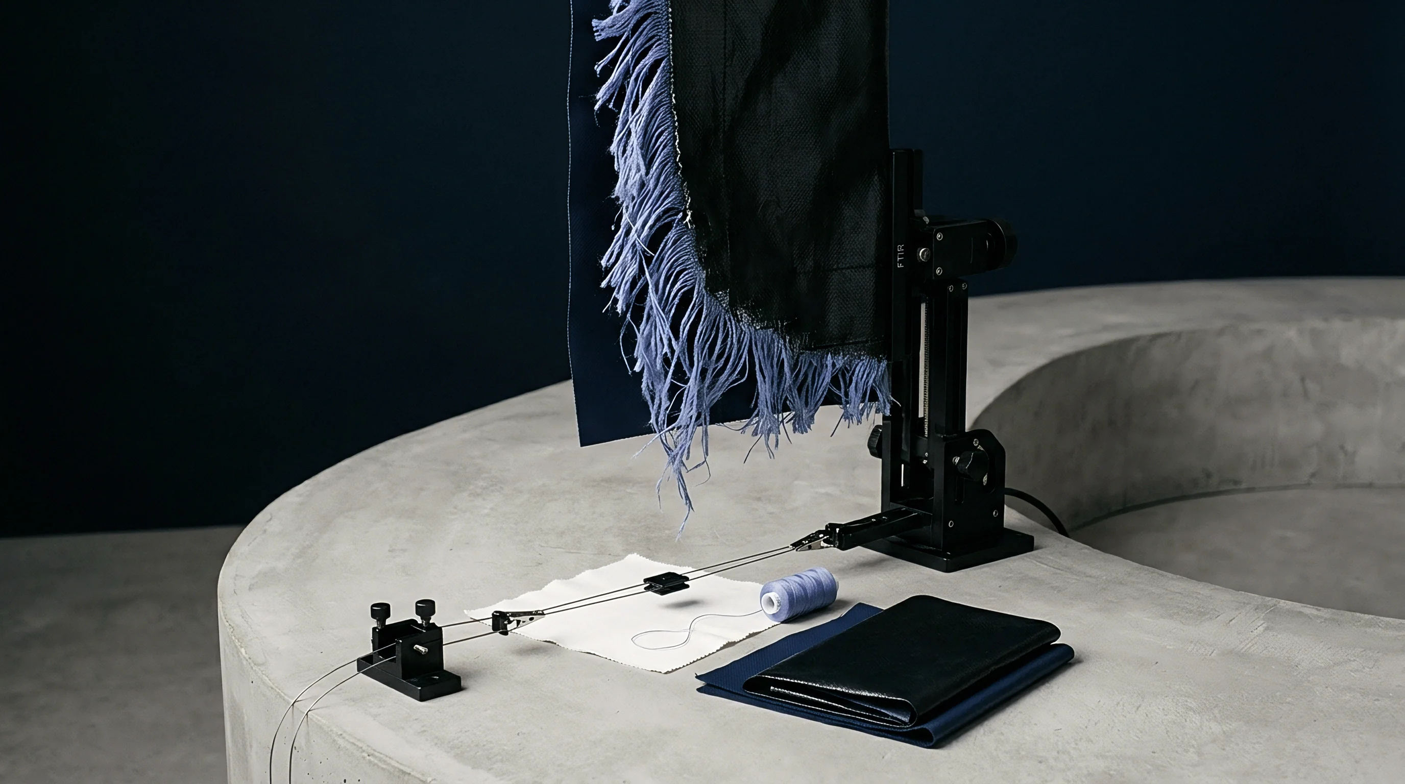
Exposure to hot aqueous media radically shifts the structural response of synthetic and natural textile fibers under dynamic physical loading. Water molecules infiltrate the amorphous regions of the polymer network, breaking inter-chain hydrogen bonds and increasing macromolecular mobility. Synthetic polymers soften above glass transition.
In polyethylene terephthalate fibers, the wet glass transition temperature drops from an dry baseline near 75°C down to approximately 65°C when fully immersed in saturated aqueous solutions. Internal residual stresses decay over time. As process temperature rises past this wet transition point toward standard dye application levels of 130°C, the elastic modulus of the amorphous polymer matrix decreases by up to 80 percent.
Under elevated thermal bath conditions, viscoelastic creep becomes the primary mechanism governing yarn strain behavior. When subjected to continuous mechanical pulling forces from liquor circulation, the softened polymer matrix undergoes irreversible macromolecular sliding. Filament yarn contracts upon heating.
The total strain response combines instantaneous elastic deformation, delayed viscoelastic strain, and permanent plastic flow. Thermal shrinkage alters crimp geometry. Modulus drops sharply near glass transition.
A continuous polyester filament yarn loaded to 0.2 cN/dtex in water at 130°C exhibits triple the total strain deformation of the same yarn tested at 20°C under identical tensile load.
Structure-Property Alterations under Aqueous Heat
The mechanical properties of textile yarns shift dramatically between dry ambient states and pressurized hydrothermal processing conditions. The table below outlines specific changes in mechanical tensile response across common textile continuous filament yarns subjected to elevated wet thermal environments.
| Fiber Polymer Type | Test Condition Temp (°C) | Tensile Modulus (cN/dtex) | Yield Strain Limit (%) | Viscoelastic Relaxation Rate (%/s) |
|---|---|---|---|---|
| Polyethylene Terephthalate (PET) | 20 (Dry) | 95.0 | 3.2 | 0.05 |
| Polyethylene Terephthalate (PET) | 130 (Aqueous Wet) | 18.5 | 1.1 | 1.42 |
| Polyamide 6,6 (PA66) | 20 (Dry) | 45.0 | 4.5 | 0.12 |
| Polyamide 6,6 (PA66) | 98 (Aqueous Wet) | 8.2 | 1.4 | 2.85 |
| Regenerated Cellulosic (Viscose) | 20 (Dry) | 60.0 | 2.0 | 0.08 |
| Regenerated Cellulosic (Viscose) | 95 (Aqueous Wet) | 6.5 | 0.6 | 3.10 |
| Methods note: Tensile modulus and yield strain measured according to modified ISO 13934-1 under submerged aqueous immersion heating up to 130°C at 50 mm/min gauge speed; relaxation rates determined from stress decay curves over 300 second holding periods at 5% fixed extension. | ||||
When operational parameters ignore the drop in wet elastic yield limit, processing fabric through high-velocity nozzles at peak hydrothermal temperatures induces permanent structural stretch that cannot be recovered during subsequent cooling steps. Tension spikes deform the yarn cross-section. Excessive draft causes width loss.
Uncontrolled permanent strain alters yarn crimp balance inside woven or knitted constructions, leading directly to irreversible post-dye fabric narrowness, poor dimensional stability, and harsh hand feel.
Computation

Finite Element Formulation of Hydrothermal Viscoelasticity
Simulating yarn strain response within a pressurized wet jet vessel requires a nonlinear finite element framework capable of coupling hydrodynamic fluid drag with structural viscoelastic constitutive equations. Yarns are discretized using spatial 3D orthotropic beam elements or multi-filament continuum shell elements that account for anisotropic mechanical behavior. The viscoelastic constitutive relationship follows a Maxwell-Wiechert linear model combined with temperature-dependent shift factors governed by the Williams-Landel-Ferry relationship.
The total stress tensor updates incrementally across discrete time steps to capture both thermal expansion and stress relaxation phenomena occurring simultaneously.
Boundary conditions within the numerical model incorporate hydrodynamic drag coefficients derived from computational fluid dynamics simulations of liquor flow past flexible cylinders. Drag forces vary dynamically as function of local yarn velocity relative to fluid stream speed, local rope compaction ratio, and instantaneous bath viscosity. Overfeed settings counteract longitudinal stretching.
The finite element solver evaluates spatial contact mechanics between adjacent yarn surfaces to account for internal bundle friction changes caused by thermal swelling and lubricant scour.
Can Finite Element Models Predict Thermal Yarn Shrinkage?
Accurate prediction of thermal yarn strain requires an explicit procedural execution workflow within the numerical solver to couple physical fluid transport with viscoelastic material laws:
- Initialize non-linear geometric domain by defining filament cross-sectional geometry, ply twist arrangement, and initial crimp amplitude from micro-tomography fabric scans.
- Map temperature dependent thermal expansion coefficients and wet viscoelastic relaxation functions onto discrete structural element integration points.
- Import localized fluid velocity vectors and static pressure fields from corresponding computational fluid dynamics transport runs.
- Apply hydro-dynamically generated axial drag forces and surface shear loads incrementally across transient time steps corresponding to nozzle passage duration.
- Solve continuous equilibrium equations using an implicit non-linear Newton-Raphson scheme to determine node displacements and internal stress tensor states.
- Update material mechanical property matrices at each node to account for temperature and water plasticization shifts during heating ramp phases.
- Evaluate plastic strain accumulation and permanent geometric distortion upon simulated thermal ramp down and vessel drain cycles.
In commercial sourcing contracts, standard clauses specifying ISO 13934 tensile performance targets without mandating submerged thermal testing fail to protect buyers against downstream structural distortion, requiring explicit finite element strain verification protocols prior to committing bulk yarn orders.

Distortion

Physical Manifestations of Uncontrolled Yarn Extension
When axial hydrothermal forces push yarns past their dynamic yield point during jet circulation, structural defects materialize in the finished fabric roll. The most severe defect is longitudinal barré, appearing as repetitive horizontal bands of variable shade depth along the fabric roll. Highly stretched yarns exhibit reduced cross-sectional diameter and altered crystalline orientation.
These physical structural changes decrease the local dye diffusion rate, producing pale horizontal streaks that become visible under standardized light box inspection after final finishing operations.
Spirality and fabric skewing also originate from unbalanced hydrothermal strain history. In circular knitted goods, longitudinal pulling during jet dyeing unbalances loop structure geometry. As yarns soft-relax under heat, stored torque releases unsymmetrically along wales and courses.
The resulting stitch distortion forces the finished fabric tube to twist out of square alignment, creating severe pattern matching errors during garment cutting room operations.
Standard ISO 6330 wash testing reveals dimensional stability failures driven by latent hydrothermal strain release, where stretched yarns contract during subsequent domestic laundering.
Strain Prediction Accuracy and Field Validation
Numerical finite element simulations provide baseline predictions for maximum strain development across varying jet machinery parameter setups. To confirm computational validity, simulated predictions must be compared directly against empirical measurements acquired under actual pressure vessel running conditions. The comparative data presented below balances finite element numerical outputs against empirical mill measurements recorded on continuous filament polyester fabric lots.
| Nozzle Diameter (mm) | Liquor Velocity (m/min) | Bath Temp (°C) | Predicted Peak Strain (%) | Empirical Measured Strain (%) | Absolute Model Variance (%) |
|---|---|---|---|---|---|
| 60 | 250 | 100 | 1.85 | 1.92 | 0.07 |
| 60 | 350 | 130 | 4.20 | 4.48 | 0.28 |
| 80 | 250 | 130 | 2.10 | 2.15 | 0.05 |
| 80 | 350 | 130 | 3.15 | 3.32 | 0.17 |
| 100 | 400 | 130 | 2.80 | 3.05 | 0.25 |
Model variance increases under high velocity, elevated temperature conditions where multi-filament bundle flattening and turbulent fluid eddy formation generate random local stress spikes not fully captured by continuum shell approximations. How should engineering teams recalibrate structural element drag coefficients when processing high-twist micro-denier yarns through non-circular nozzle geometry?
Tolerance
Operational Thresholds and Machine Parameter Control
Managing hydrothermal yarn distortion during bulk production requires precise calibration of dyehouse vessel operating parameters. Machinery technicians must set winch reel speed to match liquor flow velocity within a strict tolerance window of plus or minus 3 percent. Overfeed mechanisms on modern jet machines allow fabric feed speed to exceed reel speed by 2 percent to 8 percent, physically introducing excess slack into the storage chamber.
This intentionally applied overfeed counteracts longitudinal drag forces generated inside the venturi nozzle, maintaining net axial strain below critical yield thresholds.
Controlling pump pressure and total liquor ratio represents another frontline parameter defense. Operating at liquor ratios between 1:6 and 1:8 provides adequate hydraulic volume to cushion the fabric rope, distributing drag forces across a broader wet contact area. Lower liquor ratios below 1:4 increase internal rope friction and liquor shear stress, elevating strain deformation risk on delicate fine-denier spun goods.
Programmed cooling ramp rates of 1.0°C/min to 1.5°C/min prevent thermal shock, allowing stretched macromolecular chains to relax slowly into stable crystalline alignments before mechanical reel pulling forces strip tension from the cooling bath.
When purchasing technical fabric constructions vulnerable to thermal stretch, engineering teams establish specific quality assurance thresholds that suppliers must verify before bulk delivery:
- Maximum longitudinal strain limits cap allowable permanent fabric extension under wet thermal processing to a threshold of 2.5 percent measured against gray state greige dimensions.
- Hydrothermal stress relaxation criteria specify that yarns immersed in 130°C water for 30 minutes under 0.1 cN/dtex load maintain at least 85 percent of their initial elastic modulus.
- Dimensional change tolerances mandate post-dyeing relaxed shrinkage values below 2.0 percent in both warp and weft directions under ISO 5077 testing.
- Linear mass density uniformity requirements permit a maximum variation coefficient of 1.5 percent across continuous yarn samples pulled from processed rope heads.
Maintaining reel overfeed slightly higher than nozzle hydraulic transport draft prevents permanent longitudinal stretch across heat-sensitive filament yarns.